目录
- 目标
- 设计
- 编码
- 模块接口设计
- Verilog代码实现
- 仿真测试
- 仿真代码
- 仿真波形图
目标
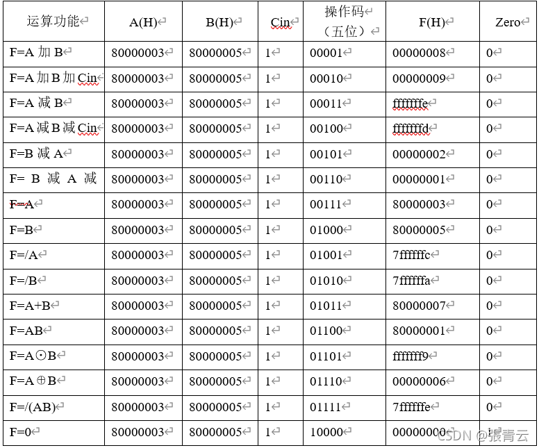
使用Verilog硬件编程语言完成一个简单的、具有执行16 种算术逻辑运算操作的电路,要求的16 种操作如下表所示:

设计
编码
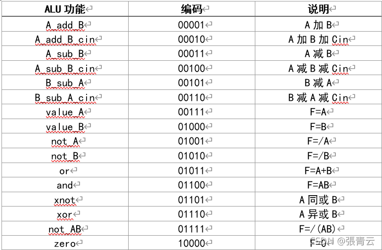
对ALU的16种运算的编码如下:
模块接口设计
信号说明如下:
• 定义四个输入信号A、B、Cin、Card。其中,A、B 为32 位运算数,Card 为5 位运算操作码,Cin 为进
位。
• 定义三个输出信号F,Cout,Zero,其中F 为运算结果,Cout 为结果进位,Zero 为零标志。
Verilog代码实现
`define T_A_add_B			5'b00001
`define T_A_add_B_cin	5'b00010
`define T_A_sub_B			5'b00011
`define T_A_sub_B_cin	5'b00100
`define T_B_sub_A			5'b00101
`define T_B_sub_A_cin	5'b00110
`define T_value_A			5'b00111
`define T_value_B			5'b01000
`define T_not_A			5'b01001
`define T_not_B			5'b01010
`define T_or				5'b01011
`define T_and				5'b01100
`define T_xnot				5'b01101
`define T_xor				5'b01110
`define T_not_AB			5'b01111
`define T_zero				5'b10000
module alu(
	input [31:0] A ,     // 操作数
	input [31:0] B ,     // 操作数
	input Cin ,				// 进位
	input [4 :0] Card,	// 控制

	output [31:0] F ,  	// 结果
	output Cout,  			// 进位
	output Zero  			// 零标识位
);

	//  保存运算结果
	wire [31:0] A_add_B_result;
	wire [31:0] A_add_B_cin_result;
	wire [31:0] A_sub_B_result;
	wire [31:0] A_sub_B_cin_result;
	wire [31:0] B_sub_A_result;
	wire [31:0] B_sub_A_cin_result;
	wire [31:0] value_A_result;
	wire [31:0] value_B_result;
	wire [31:0] not_A_result;
	wire [31:0] not_B_result;
	wire [31:0] or_result;
	wire [31:0] and_result;
	wire [31:0] xnot_result;
	wire [31:0] xor_result;
	wire [31:0] not_AB_result;
	wire [31:0] zero_result;

	//  进位
	wire [1:0] Cout_a;
	wire [1:0] Cout_b;
	wire [1:0] Cout_c;
	wire [1:0] Cout_d;
	wire [1:0] Cout_e;
	wire [1:0] Cout_f;

	//  如果是运算后立即赋值,而被赋值变量较宽,则按被赋值的变量宽度计算
	assign {Cout_a, A_add_B_result} = A + B;
	assign {Cout_b, A_add_B_cin_result} = A + B + Cin;
	assign {Cout_c, A_sub_B_result} = A - B;
	assign {Cout_d, A_sub_B_cin_result} = A - B - Cin;
	assign {Cout_e, B_sub_A_result} = B - A;
	assign {Cout_f, B_sub_A_cin_result} = B - A - Cin;
	assign value_A_result = A;
	assign value_B_result = B;
	assign not_A_result = ~A;
	assign not_B_result = ~B;
	assign or_result = A | B;
	assign and_result = A & B;
	assign xnot_result = ~(A ^ B);
	assign xor_result = A ^ B;
	assign not_AB_result = ~(A & B);
	assign zero_result = 0;

	//  计算结果:通过Card值的不同,在多个计算结果中选择一个赋值给F
	assign F = 	({32{Card == `T_A_add_B}} & A_add_B_result) |
					({32{Card == `T_A_add_B_cin}} & A_add_B_cin_result) |
					({32{Card == `T_A_sub_B}} & A_sub_B_result) |
					({32{Card == `T_A_sub_B_cin}} & A_sub_B_cin_result) |
					({32{Card == `T_B_sub_A}} & B_sub_A_result) |
					({32{Card == `T_B_sub_A_cin}} & B_sub_A_cin_result) |
					({32{Card == `T_value_A}} & value_A_result) |
					({32{Card == `T_value_B}} & value_B_result) |
					({32{Card == `T_not_A}} & not_A_result) |
					({32{Card == `T_not_B}} & not_B_result) |
					({32{Card == `T_or}} & or_result) |
					({32{Card == `T_and}} & and_result) |
					({32{Card == `T_xnot}} & xnot_result) |
					({32{Card == `T_xor}} & xor_result) |
					({32{Card == `T_not_AB}} & not_AB_result) |
					({32{Card == `T_zero}} & zero_result);

	//  判断是否产生进位
	assign Cout = 	(Card == `T_A_add_B && Cout_a != 0)|
						(Card == `T_A_add_B_cin && Cout_b != 0) |
						(Card == `T_A_sub_B && Cout_c != 0) |
						(Card == `T_A_sub_B_cin && Cout_d != 0) |
						(Card == `T_B_sub_A && Cout_e != 0) |
						(Card == `T_B_sub_A_cin && Cout_f != 0);
	//  判断结果是否位0
	assign Zero = F == 0;

endmodule
仿真测试
这里我们将A固定为{1’b1, 31’b11},B固定为{1’b1, 31’b101},通过改变Card的值来观察执行不同操作时的输出。
仿真代码
module alu_tb;

	// Inputs
	reg [31:0] A;
	reg [31:0] B;
	reg Cin;
	reg [4:0] Card;

	// Outputs
	wire [31:0] F;
	wire Cout;
	wire Zero;

	// Instantiate the Unit Under Test (UUT)
	alu uut (
		.A(A),
		.B(B),
		.Cin(Cin),
		.Card(Card),

		.F(F),
		.Cout(Cout),
		.Zero(Zero)
	);

	initial begin
		// Initialize Inputs
		A = {1'b1, 31'b11};
		B = {1'b1, 31'b101};
		Cin = 1;
		Card = 5'b00001;

		// Wait 100 ns for global reset to finish
		#100;

		// Add stimulus here

	end

	always #10 Card = (Card + 1) % 16 == 0 ? 16 : (Card + 1) % 16;

endmodule
仿真波形图
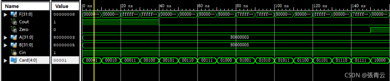
结果如下: